Inżynier i Fizyk Medyczny 5/2016 vol. 5
279
artykuł
/
article
radioterapia
/
radiotherapy
MV isocenter is less than 0.25mm. The XVI system application is based
on one of twomethods of “searching” of the ball centre, to refer it posi-
tion to theMV isocenter (it’s up to the user, which onewill be used). One
of thesemethods is based on detecting of the edge of the high contrast
object (sri.ini file). The second of these methods (default) is based on
detecting of the pixel signal intensity and searching of the ball mass
centre. Due to the BB phantomdesign the analysis of the pixel intensity
for the transverse dimension is performed in the both directions sym-
metrically and for the longitudinal dimension in the one direction only.
This is due to the fact that in the longitudinal dimension themetal ball is
placed in the “asymmetrical environment” fromthe imaging/pixel value
point of view (on one side the air and on the other side the material of
the BB phantom arm - perspex). To increase the accuracy of the algo-
rithm, the system has built-in information of the expected coordinates
pixel/voxel to spot the ball mass centre. The 3D CBCT acquisition of the
BB phantom provides the u and v dimensions of the elliptical drawn
through the centre of the ball phantom in the projections for different
gantry angles (u and v should be less than 9.0 mm in line with technical
documents). The flexmap is introduced. It seems that tolerance – 9.0
mm- is greatly exaggerated. Change of the u and v values of about 1.0
mm (eg. from2.73mm to 3.63mm) deteriorate image quality by an one
pattern group of a spatial resolution test. It is important to know that
the calibration of the flexmap compensates the effects of gravity de-
flection of the systemcomponents and their relative positions at differ-
ent gantry angles. The flexmap correction can be improved in terms of
the image quality. That can be done by “making” the shift of all flexmap
coordinates by the same value, eg. 0.3 mm. This is based on the calcu-
lation of offset which is needed to add/subtract from flexmap values
to get the best possible compensation of deviation of the circular tra-
jectory. The result of this shift should be assessed using of the imaging
quality parameters (particularly the spatial resolution). The shift can be
increased by an another value, eg. 0.2 mm. The summary shift can’t be
bigger than 1.0 mm. It is also very important to verify whether the flex-
map for each FOV and direction of rotation has correction factors in the
full range of gantry rotation (the difference between the start point
and end point must be less than 1 deg).
PANEL POSITION CALIBRATION -
SPATIAL RESOLUTION & UNIFORMITY
The panel positioning in the lateral direction turned out to be a critical
in terms the image quality. Improper calibration of the panel position
with shift of 1.0 mm in the lateral direction for each FOV resulted in
a “dramatic” deterioration of the spatial resolution (Fig. 17) and uni-
formity results. Those results of performed tests and calibrations
determined final conclusion that the image quality should be verified
for each FOV (extended CAT). It seems to be logical for a simple rea-
son: each FOV has its own set of calibration - the position of the panel
(the pots voltage readings), flexmaps, gains. The spatial resolution
test proved to be a very sensitive tool to evaluate the correct position
of the panel, flexmap calibration and scaling. Fig. 17 shows obtained
apparent differences in the image quality caused by 1.0 mm of lateral
offset in the panel position. Offset by 0.5 mm in the same direction
reduced the visibility the spatial frequency patterns expressed in pl/
cm by 2-3 groups. The expected position of the panel is determined
by the FDK reconstruction algorithm, which is very strictly defined in
the coordinates of the XVI system in terms of the panel/pixel position,
SDD and X-ray beamalignment. Any interference in the settings of the
lateral panel position, SDD and X-ray beam alignment causes neces-
sity to run again the bad pixel calibration, gain calibration, flexmaps
and finally the evaluation of the image quality. The procedure has to
be repeated if result is not positive.
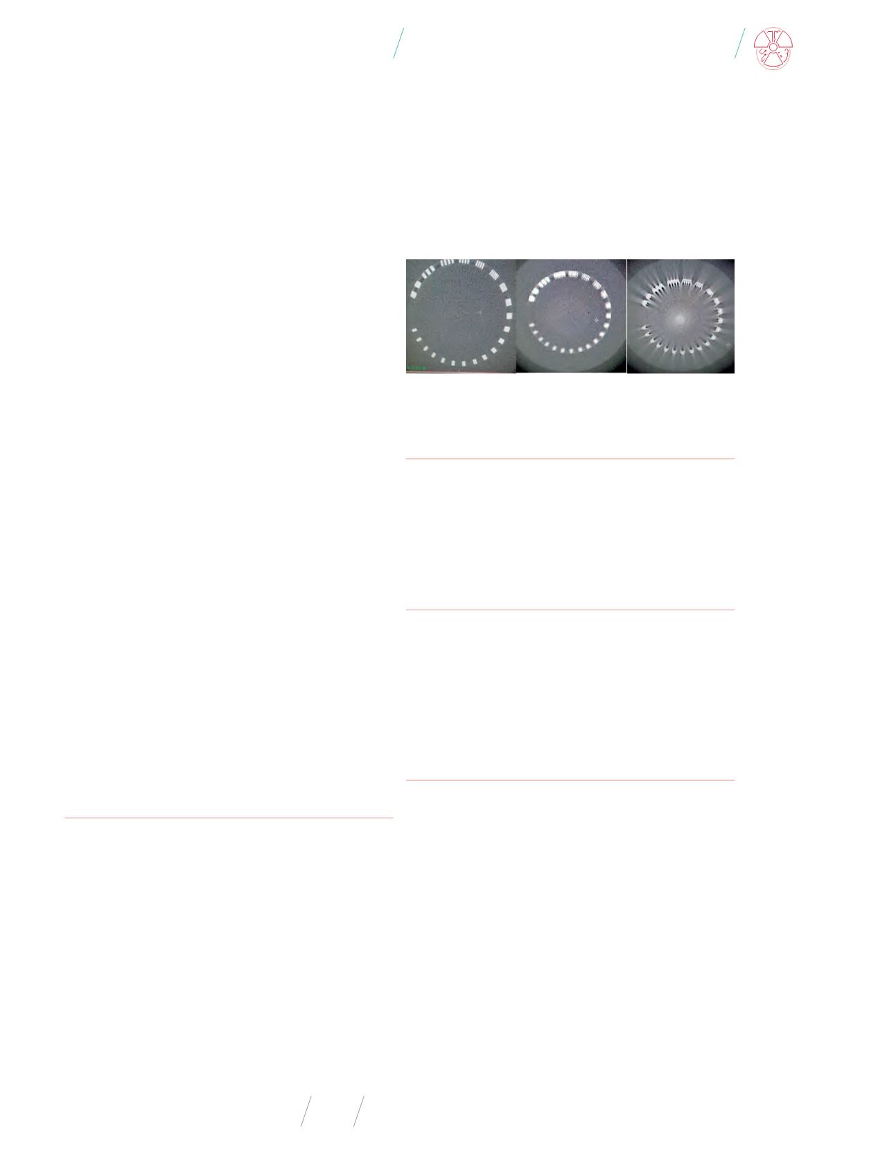
Fig. 17
. Spatial resolution of SFOV , MFOV and LFOV – results for system calibrated
in line with technical manuals (without calibration of lateral panel position)
Source: Own results.
RESULTS
Spatial resolution:
SFOV – 14.5 pl/cm ; MFOV – 13.0 pl/cm; LFOV
– 14.5 pl/cm
Uniformity:
SFOV - 0.74% ; MFOV - 2.24% ; LFOV - 3.40%
Contrast:
SFOV – 1.87% ; MFOV – 2.33% ; LFOV – 2.84%
CNR:
SFOV – 4.9 ; MFOV – 3.9 ; LFOV – 3.8
CONCLUSION
Introducing extended CAT for the XVI (R.5.0.2) Elekta system pro-
vides full evaluation of that system before introducing it to clinical
practice and ensures that image quality is acceptable for all FOVs.
The new calibration procedure and newmethodology of verification
of the system results significant improvement image quality and
getting proper reconstruction of image information.
REFERENCES
1.
J. Starman:
Lag correction
in
amorphous silicon flat
-
panel x
-
ray
computed tomography. A disseration submitted to the Department
of Electrical Engineering and the Committee on Graduate Studies
of Stanford University in partial fulfillment of the requirements for
the degree of Doctor of Philosophy
, Msc Thesis, 2010.
2.
XVI R5.0 Corrective Maintenance Manual.
3.
Ch.C. Shaw:
Cone Beam Computed Tomography
, CRC press.
4.
5.
-
cordOId=2156983&fileOId=2157374.
6.
D. Oborska-Kumaszynska et al.:
Testy kontroli jakości I kalibrac-
ja system XVI Elekta Synergy, cz.1
., Inżynier i Fizyk Medyczny,
2, 2013, 195-200.
7.
D. Oborska-Kumaszynska et al.:
Testy kontroli jakości I kalibrac-
ja system XVI Elekta Synergy, cz.2
., Inżynier i Fizyk Medyczny,
2, 2013, 235-242.
8.
D. Oborska-Kumaszynska, D. Northover:
Optymalizacja sys-
temu XVI dla protokoł
ó
w klinicznych,
Inżynier i Fizyk Medyczny,
5, 2016, 203-215.


