vol. 5 5/2016 Inżynier i Fizyk Medyczny
278
artykuł
\
article
radioterapia
\
radiotherapy
FLEXMAP & MANUAL
OFFSET CORRECTION
One of the most important test and calibration of the XVI system is
that the center of rotation is correct i.e. that the X-ray source and im-
aging panel rotate in a perfect circular trajectory in relation to each
other. The deviation from perfect isocentric rotation is called flex
and correction has to be introduced to compensate it. When display-
ing the flex as a function of the gantry angle a flexmap is obtained
(Fig.13-15). Due to the weight of the accelerator head and the addi-
tional weight of the kV x-ray tube along with its flat panel detector,
investigation of the flexmaps in the gantry rotation is required. The
weight causes perturbations in the circular scanning trajectory. Al-
though relatively small shift (the typical flexmap values - u and v - are
2.4-3.8 mm) seems like it can be neglected it produces a significant
image distortion, degradation of spatial resolution and misshaping
of imaged test objects (Fig. 12)
Fig. 12
. Example of CATPHAN phantom image with misshaped test objects
Source: Own results.
Flexmap calibration is performed using a Ball Bearing phantom
(BB Phantom). That phantom is constructed with perfectly spheri-
cal metal ball (a high atomic number material), mounted at the end
of a long perspex rod. The rod is mounted on a system with vernier
mechanisms which allowmovement of the rod and ball in all three di-
rections with precision of 0.01 mm. The same phantom can be used
to verify the registration of 3D image (CBCT vs CT) and flexmap cal-
ibration. The flexmap function is taken into account in the 3D image
reconstruction and is “added” to the projection before the “achieve-
ment” the reconstruction algorithm “mechanisms”.
After positioning of the phantom the imaging detector and X-ray
tube as well as EPI system should be pulled out to the imaging posi-
tion. It should be remembered that the XVI imaging panel must be
deployed at the gantry 0 deg due to the panel lateral position and
the pots’ readings for all FOVs are calibrated at that particular gan-
try angle. There is also important to use the particular buttons on
the remote pendant to move the panel to each FOV (MFOV – “open
button”, SFOV- “Lateral movement button small FOV direction”,
LFOV – “Lateral movement button large FOV direction”). It is as-
signed to accuracy of the pots readings and panel positioning and
finally high image quality (spatial resolution and uniformity).
The MV projections (iView) of the BB phantom for four gantry po-
sitions and for each of the two positions of the collimator 90 and -90
degrees (IMRT field, 8 segments, frame averaging) have to be acquired.
Those projections are exported to the XVI system and the ball centre
displacement is calculated relative to MV system isocenter. When dif-
ference is greater than 0.25 mm then the correction using a vernier has
to be done accordingly to calculated offsets. The direction and distance
of the ball is indicated in the table. At the same time these values “rep-
resent” the relative position of laser isocenter and accelerator radiation
isocenter. After correction of the ball position the MV projections have
to be acquired to check if offset between the ball centre positon and
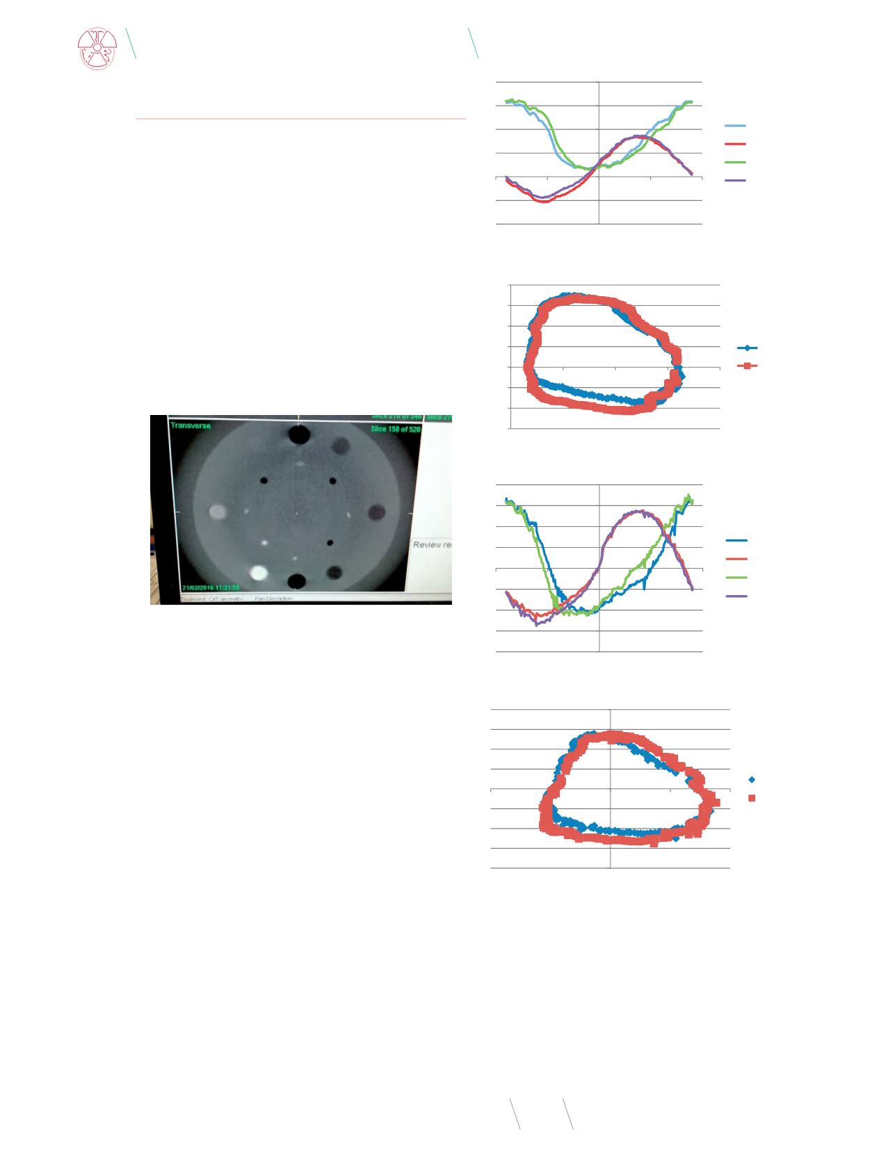
Fig. 13
. Flexmap - MFOV – u and v vs gantry angle
Source: Own results.
‐2
‐1
0
1
2
3
4
‐200
‐100
0
100
200
X_CC (mm)
Y_CC (mm)
X_CW (mm)
Y_CW (mm)
‐1,5
‐1
‐0,5
0
0,5
1
1,5
2
0
1
2
3
4
CW [mm]
CC
‐2
‐1,5
‐1
‐0,5
0
0,5
1
1,5
2
‐200
‐100
0
100
200
X CW [mm]
Y CW [mm]
X CC [mm]
Y CC [mm]
‐2
‐1,5
‐1
‐0,5
0
0,5
1
1,5
2
‐2
‐1
0
1
2
CW [mm]
CC [mm]
Fig. 14
. Flexmap - MFOV – u vs v . (smooth shape)
Source: Own results.
Fig. 15
. Flexmap - SFOV - u and v vs gantry angle
Source: Own results.
Fig. 16
. Flexmap - SFOV - u vs v (visible offset “points” in ellipsoidal shape)
Source: Own results.


