vol. 5 5/2016 Inżynier i Fizyk Medyczny
274
artykuł
\
article
radioterapia
\
radiotherapy
INTRODUCTION
Cone-beam CT (CBCT) has rapidly became the standard equipment
in radiation therapy employing image-guided radiation therapy
(IGRT) for patient position verification. A X-ray tube and amorphous
silicon detector panel with a cesium iodide scintillator layer of a XVI
system (X-ray Volumetric Imaging System) are installed opposite in
relation to each other on a linac gantry drum and perpendicular to
a linac head and EPID. The XVI system rotates together with the gan-
try of the accelerator around their common isocenter. The system
is used to acquire and reconstruct 3D volumetric images to verify
a patient position during a RT procedure. The advent of three-di-
mensional imaging and visualization during treatment has provided
new opportunities and challenges for improved patient positioning.
A reconstruction process is based on 650 planar projections, taken
during a full rotation of the gantry (360 degrees) or about 330/350
projections for the half rotation (180 degrees).
The quality of the CBCT reconstruction is inferior to the quality
obtained using the CT systems. The worse CBCT image quality can
be attributed to few source of mechanisms: a fan beam and signifi-
cant contribution of scatter radiation, an image detector technology
and quality, lag and ghosting, geometry of a CBCT system, a recon-
struction algorithm and methodology of a calibration procedure.
For example, scatter results in occurrence of cup and streak artifacts
as well as cuases degradation of contrats in the CBCT image. Bad pix-
els and bad pixel lines in the kV imaging panel may result in ring arti-
facts and worse image uniformity. They can also affect the quality of
2D images. For example, it can result blurring or occurrence of not
corrected bad pixels as a “black” or “white” single or linear artifacts.
Residual signals from previous acquisitions when visible on newly
acquired images may result in ghost artifacts. The lag and ghosting
issues of indirect detectors (Perkin-Elemer panel) can be attribut-
ed to three source of mechanisms: charge trapping and release in
a-Si photodiode; after-glow CsI scintillator and incomplete read-
out of charge from the pixel to the charge amplifiers. In terms of
all possible sources contributing in the image quality, both pre- and
post-reconstruction methods as well as calibration process should
to alleviate the effects of various artifacts on CBCT image quality.
PANEL ALIGNMENT
XVI system geometry affects every factor of imaging performance.
There is not only a SDD distance in terms of magnification, contrast,
noise, scatter and spatial resolution. There is also panel alignment in
relation to X-ray beam. Importance of a panel setup – perpendiculari-
ty of a panel surface as well as a lateral and longitudinal panel position
- is determine by a reconstruction algorithm. 3D volumetric data are
directly reconstructed from the two-dimensional projection data in
cone-beam geometry. The FDK algorithm is the approximate recon-
struction technique for cone-beam projections about a fixed isocen-
ter acquired along a circular trajectory. In this method, the measured
cone-beam projections are pre-weighted, filtered and finally back
projected along the same ray geometry as initially used for forward
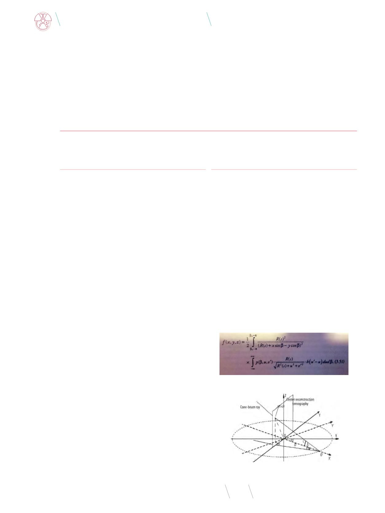
projection. The FDK reconstruction algorithm for cone beam image
reconstruction is strictly assigned to a helical trajectory or general
trajectory in the Cartesian coordinate system (Fig. 2). A generalized
FDK algorithm is expressed as follows - the pre-weighted projection
data for each projection angle is back projected and then summed up
to a reconstructed voxel of coordinates (x, y, z) and represented as:
Calibration and optimisation
of a XVI System (Elekta Synergy)
– Pitfalls
Dominika Oborska-Kumaszyńska
Wolverhampton Royal Hospitals, New Cross Hospital, MPCE Department, Wolverhampton, United Kingdom, e-mail:
Fig. 2
. Geometric coordinates of CBCT scan
Source: [4].
Fig. 1
. The generalized FDK algorithm formula
Source: [3].


